Postage free from 99€ (DE)
High customer satisfaction


 DE | €

- Scooter 50-850cc
- Royal Alloy Horn for GP, GT, JPS, TG

Genuine Royal Alloy 12V electric horn for various models from the GP, GT, JPS and TG ranges. The horn is part of the standard electrical signalling system and is used to provide an audible warning signal to alert other road users when required.
The genuine replacement part with Royal Alloy part number 0311020004-02-001 is suitable for replacing a defective, damaged or no longer reliably functioning vehicle horn. Its design corresponds to the configuration intended for the respective Royal Alloy models, with a round sound unit, two electrical blade terminals and an integrated mounting bracket.
The horn operates according to the electromagnetic principle. When the horn button is pressed, electrical voltage is supplied to the sound unit. An electromagnetic drive causes a diaphragm to vibrate, thereby generating the audible warning signal.
Electrical power is supplied by the scooter's 12V electrical system. The horn is designed for use within the standard vehicle electrical system and is operated via the existing horn switch.
Unlike an electronic signal horn with separate control electronics, this version is a conventional electromagnetic sound unit with a compact, round housing design.
Its construction allows the sound unit to be installed in the designated mounting position on the vehicle.
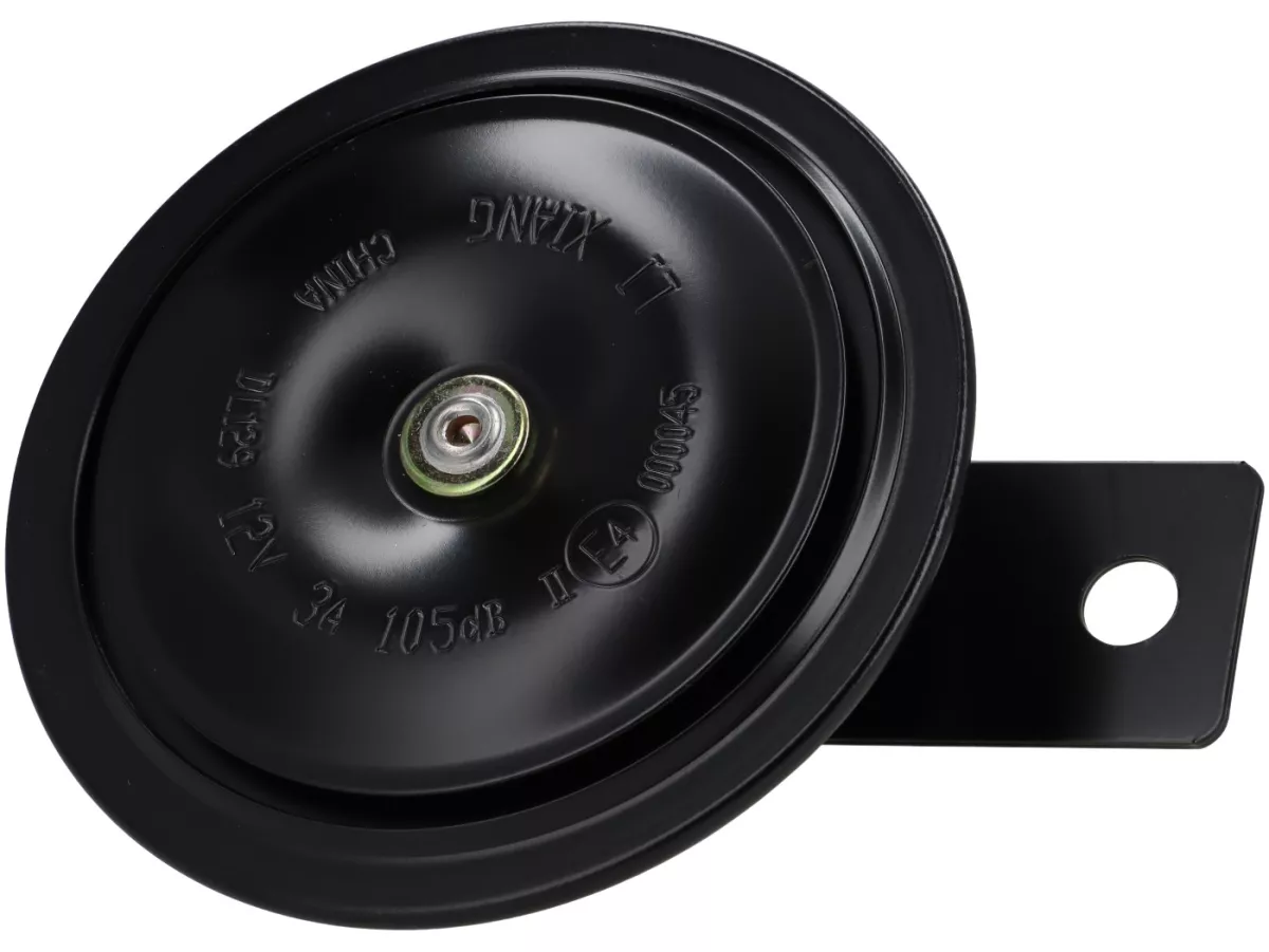
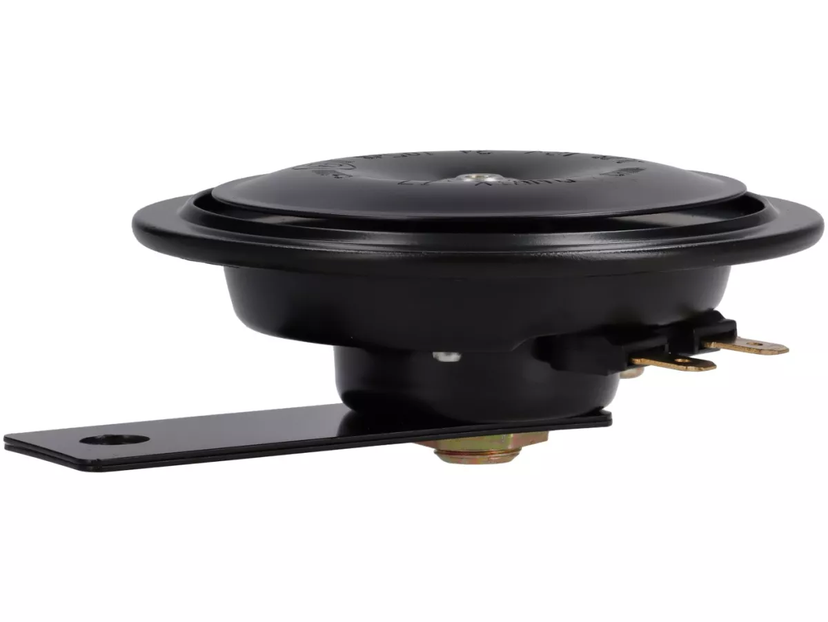
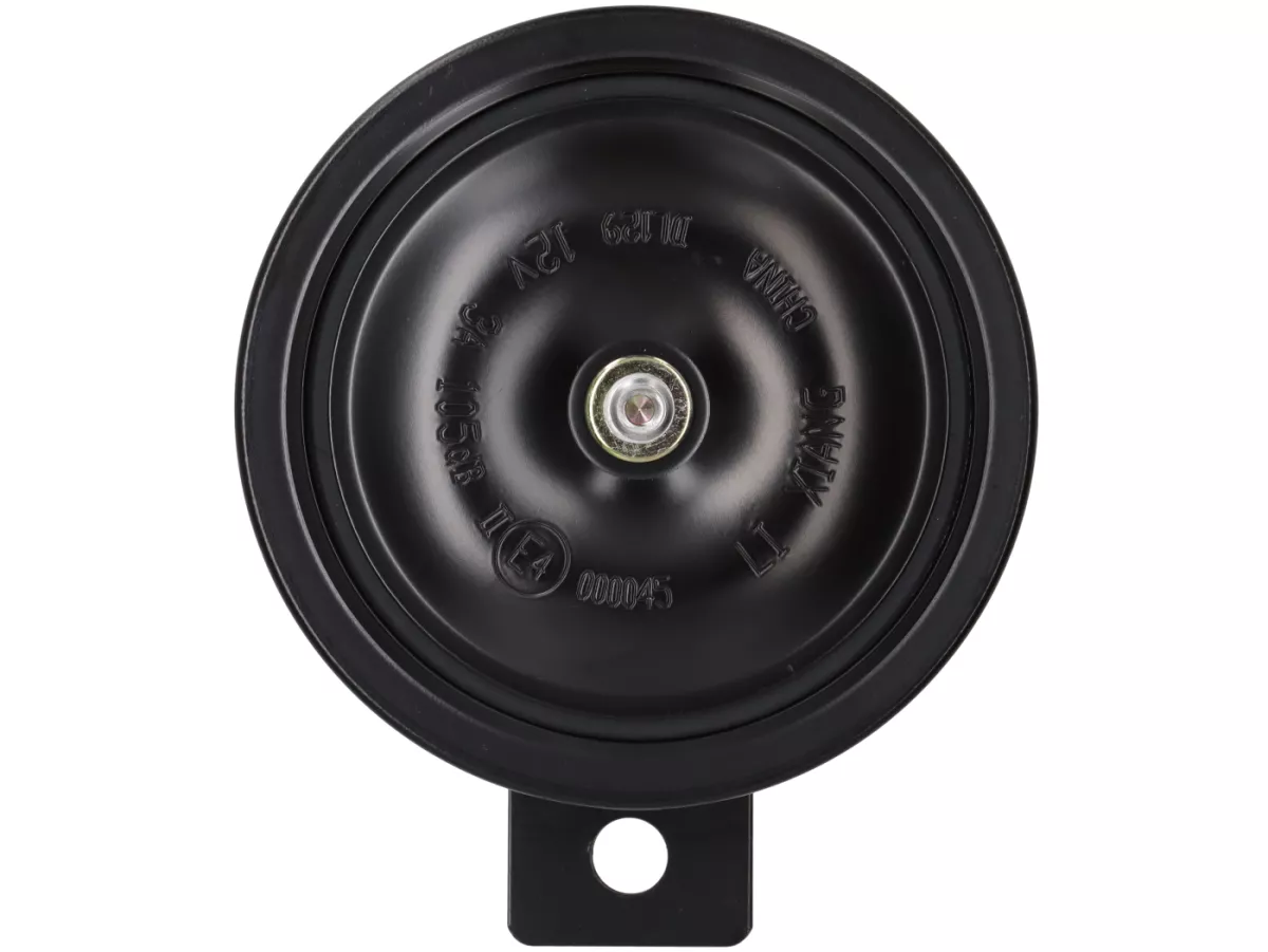
The horn housing consists of a flat, round metal construction with a black surface coating.
The front features a convex circular cover. Several concentric recesses and a continuous outer rim define the shape of the housing.
A metallic fastening point is located in the centre of the front. Various embossed markings are arranged around it.
The markings visible on the front include:
The 12V marking indicates the electrical operating voltage. The 3A specification is embossed on the housing as a current rating.
The 105dB marking is a sound level specification shown on the component. However, without additional information regarding the measuring procedure and measuring distance, this value cannot be used to determine a directly comparable sound pressure level when installed on the vehicle.
The embossed E4 mark indicates a corresponding type-approval marking. The precise classification and validity of the approval depend on the complete approval number and the associated approval documentation.
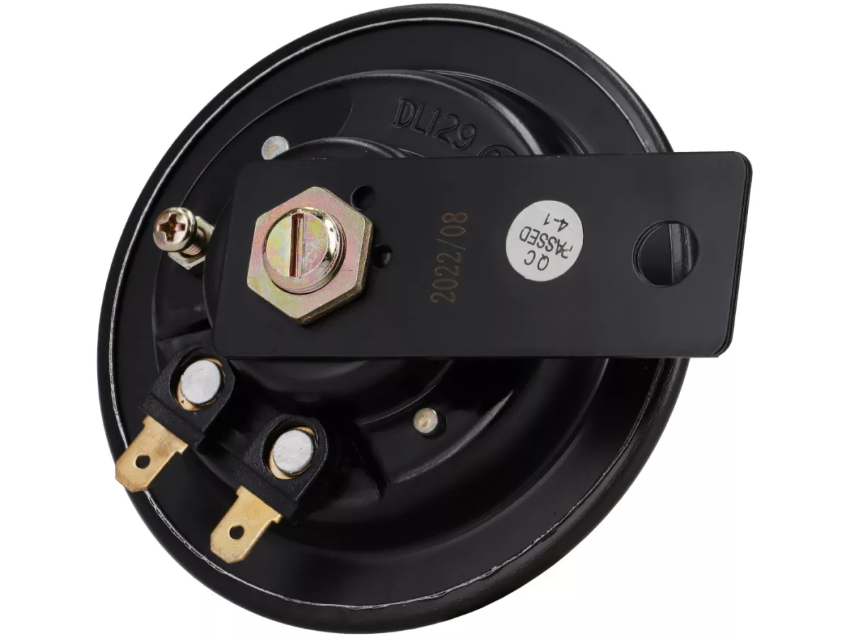
The horn's electrical connection assembly is located on the rear.
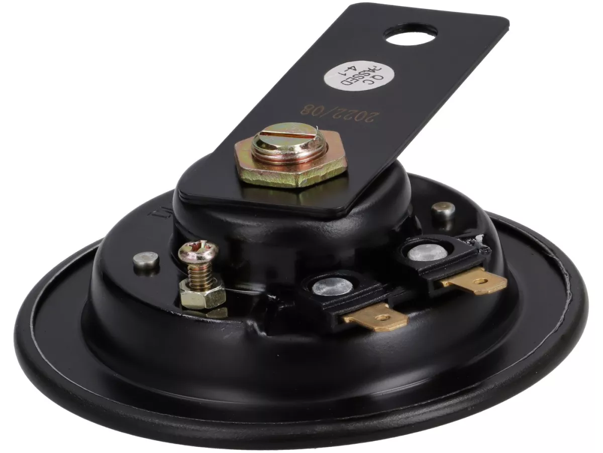
Two parallel metal blade terminals extend laterally from the rear housing section. The terminals have a gold-coloured metallic finish and each features a small opening near its outer end.
Both terminals are mounted in black insulating holders and are used to connect the vehicle's electrical wiring.
This design allows a plug connection using the corresponding female terminals of the original wiring harness.
When replacing the horn, make sure that the blade terminals are clean, undamaged and free from corrosion. The connectors must fit securely onto the terminals to ensure a reliable electrical connection.
Damaged or loose electrical connections can result in impaired operation or complete failure of the warning signal.
The horn is equipped with a flat, black-coated metal mounting bracket.
The bracket extends outward from the centre of the rear housing and has a round mounting hole at its free end.
This hole is used to secure the horn to the designated mounting point on the vehicle.
The bracket is connected to the sound unit by a central fastening with a hexagonal nut and metal screw connection.
The bracket is already fitted to the horn and forms a compact assembly together with the sound unit.
The horn must be installed so that the housing has sufficient clearance from adjacent vehicle components and is not subjected to mechanical pressure from body panels or other parts.
Installation under tension or direct contact with neighbouring components can affect the vibration characteristics and therefore the acoustic function of the horn.
A small Phillips-head screw with a locknut is located on the rear next to the two electrical terminals.
On electromagnetic horns of this type, such a screw connection is typically used for the factory adjustment of the vibration system.
This adjustment influences the interaction between the electromagnetic actuation and the vibrating diaphragm.
Changing this setting is not required during normal replacement and should be avoided unless corresponding manufacturer specifications are available.
An embossed component marking and a date marking can also be seen on the rear. An additional sticker documents a quality control check.
These markings are used for component identification and traceability.
The electric horn is intended for various Royal Alloy models from the GP, GT, JPS and TG ranges.
Royal Alloy genuine part number 0311020004-02-001 is documented in spare parts diagrams for the following model variants, among others:
This horn is also listed as a replacement part for further versions of the GP, GT and TG ranges.
As the electrical equipment and installation arrangement may vary depending on the model and year of manufacture, compatibility should be checked against the Royal Alloy genuine part number before ordering.
A defective horn may be indicated by a complete absence of the warning signal, intermittent operation or a noticeably altered sound.
However, the cause does not necessarily lie in the sound unit itself. A defective horn switch, corroded connectors, damaged wiring or an insufficient power supply can also impair operation.
The electrical supply and connections should therefore be checked before replacing the horn.
Before removal, the electrical system must be disconnected from the power supply in accordance with the manufacturer's instructions.
The two electrical connectors can then be disconnected and the mounting bracket fastening removed.
The new horn is secured to the designated mounting point on the vehicle. Care must be taken to ensure that it is installed without mechanical tension and with sufficient clearance from adjacent components.
After connecting the electrical wiring, check that the connectors are securely fitted and that the cables are neither trapped nor subjected to excessive tension.
Finally, the horn should be function-tested using the horn button on the handlebar.
When operated, the horn must produce a consistent and clearly audible warning signal.
The Royal Alloy 12V electric horn can be used to restore the standard audible warning system on various GP, GT, JPS and TG models.
The round metal construction, two rear blade terminals and integrated mounting bracket correspond to the intended design of the original component.
Royal Alloy genuine part number 0311020004-02-001 provides clear identification of the replacement part and helps ensure selection of the correct horn for the respective vehicle.