In today’s video and blog, we talk about measuring inlet timing, also referred to as inlet duration. Inlet timing should fall within a specific range, indicated in degrees of crankshaft rotation. Measurements are always taken from the top dead center, abbreviated as TDC.
The inlet phase is therefore divided into values “before TDC” and “after TDC”, since the inlet opens before TDC and closes after passing TDC.
For a Vespa rotary valve engine, optimal touring specs are around 100° BTDC and 65° ATDC. High-performance setups, which require higher RPMs, may go up to 120° BTDC and 75° ATDC. Choose your inlet timing to suit your engine concept. The basic rule: make the inlet duration as long as necessary, but as short as possible for optimal carburetor tuning and power delivery.
Platonika’s two-stroke engine is intended to deliver strong acceleration, so the target inlet timing is 100° BTDC to 65° ATDC.
To precisely measure inlet timing, you'll need some tools and materials:
• Engine case
• Crankshaft
• Cylinder and piston
• Dummy bearings
It’s often necessary to modify the inlet area in the engine case to achieve the desired timing. Dummy bearings allow you to install and remove the crankshaft repeatedly without damaging the bearing seats.
These dummies are available in all common sizes used in Vespa and Lambretta engines. First, insert the dummy bearings into the engine case, then slide the crankshaft into the dummies and bolt the case together via the stator studs.
Measuring
To find TDC, insert the piston without rings into the cylinder. Mount the dial gauge to the cylinder using the holder to identify exact TDC.
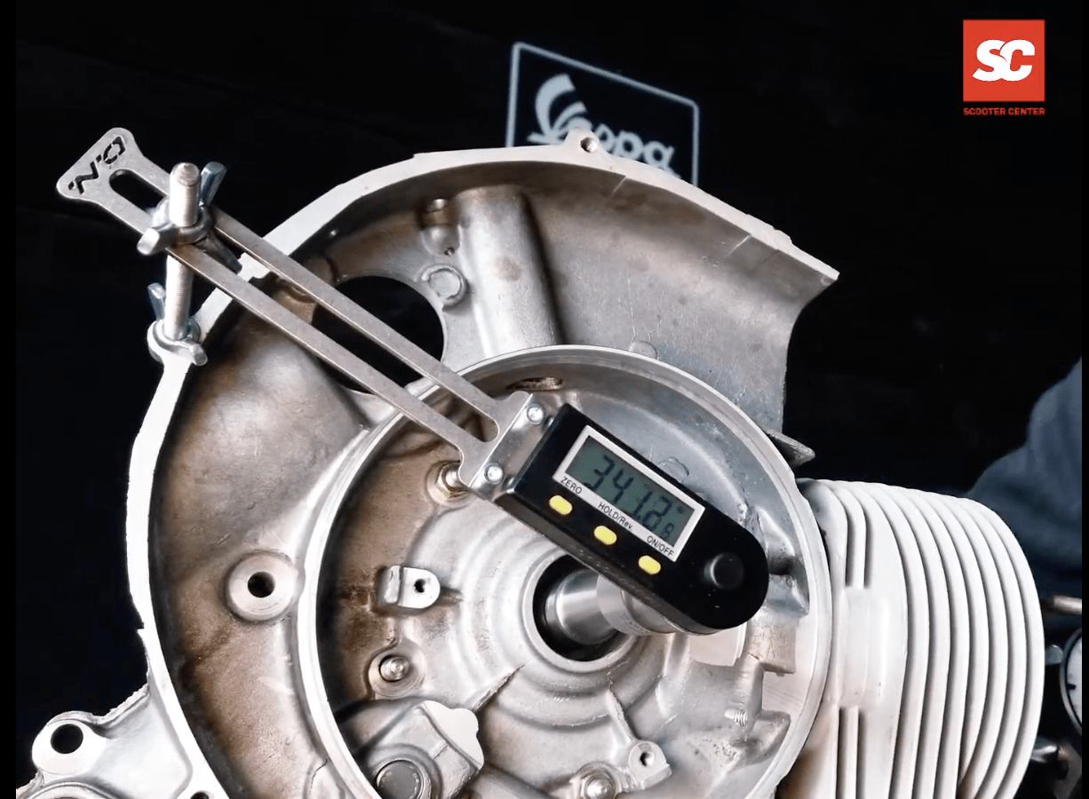
Attach a degree disc or digital protractor to the flywheel side. Many options exist, but digital tools like the Buzz Wangle are easiest since they don’t require referencing the engine case.
With the crankshaft at TDC, set the degree disc to “0” and rotate the crankshaft to inlet opening and closing positions. The measured values indicate when the inlet opens and closes.
Increasing Inlet Duration
To enlarge the inlet, rotate the crankshaft to the desired values and mark the crank web’s position on the engine case.
Mark both the opening and closing points, open the case again, and remove the crankshaft using the dummy bearings.
Be cautious when modifying the inlet area: there must be at least 1mm overlap between crankshaft and sealing surfaces to maintain proper rotary valve sealing.
Once the inlet is ground to the marked positions and the case is cleaned, reinsert the crankshaft to verify the timing.
Use the degree disc to check whether the target angles are reached or if further adjustment is needed.
 DE | €

 - Vespa Primavera 50 3V iGet (Euro5), Sprint 50 iGet (Euro5), Piaggio Liberty 50 iGet (Euro5) order online!")

, DL, GP, J, Lui browse online now!")


